
Servo controllers serve as the interface between the PC and the servo motors.
Update: The current version of VSA now has native support for the Maestro controllers! I am currently verifying that this works, and will update shortly…
First, a little history.
Scott Edwards Electronics Mini Serial Servo Controller II (Mini SSC II)
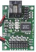 The Mini SSC II was an 8-channel servo controller that connected to PCs via a now obsolete RS-232 serial port. It was the first of these controllers to become popular, and a number of software packages were designed to for it. One of these was the package we use – Visual Show Automation (VSA). This is important because many of the newer, USB-based servo controllers are not directly supported by VSA. However, these new controllers often have an emulation mode where they will accept the old Mini SSC commands. We will sometimes need to use this.
The Mini SSC II could control up to 8 servos. With each servo, you could command it to go to one of 255 different angular positions (0-254). Most servos will turn about 90 degrees using a standard control signal, so commanding 0 would be -45 degrees, and command ing 254 would move to +45 degrees. The Mini SSC also had an extended range mode that would try to drive the servo a full half turn (+/-90 degrees). Unfortunately, most servos simply can’t go this far. So you had to be careful not to drive the servo beyond it’s limits. On many servos, if you command a position beyond what it can reach, it will just push as hard as it can against itself until it burns out. Fortunately VSA lets you easily set the limits for each servo to make sure this doesn’t happen. Besides this overdriving problem, the extend range mode meant each of those steps was twice as large, making it harder to get smooth-looking motion.
Modern USB-based servo controllers are powered from the USB port. However, the servos themselves are not. The controller boards have a place to connect servo power, which you must provide. We’ll have more to say about this later.
Here are the modern controllers we recommend:
Parallax Propeller Servo Controller USB
 The Parallax Propeller Servo Controller USB is a modestly priced, easy to use, 16-channel servo controller. It is directly supported by VSA.
When you first plug the USB cable in, Windows should automatically install the required FTDI USB driver. When it begins installing, click on the alert to monitor the progress. It should install a new COM port. Note the number (e.g. COM4, COM5, etc.).
In VSA settings, you will need to select the Parallax device and the COM port. Under ports, you will also want to verify that this COM port is set to 38400 baud.
Servo power must be connected to the screw terminals. The switch on the board turns servo power on and off. This is a nice feature, allowing you to power down the servos without having to unplug stuff.
The Parallax boards allow you to send position commands from 250 to 1250. This should correspond to a range of +/-90 degrees on the servos. Again, you need to manually set the limits so as not to burn out your servo by asking it to do something it can’t do.
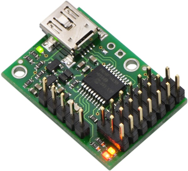 The Pololu Maestro series of USB servo controller boards are inexpensive, well supported, highly capable devices. They come in 6, 12, 18 and 24 channel versions, allowing you to buy only as much controller as you need.
Although VSA supports one of the older Pololu controllers, the newer Maestro series is only supported via Mini SSC emulation. (Hopefully, this will change in a future version of VSA.) In VSA’s settings, you will need to select the Mini SSC controller, along with the correct COM port. You do not need to set anything on the board – the emulation is automatic.
Before plugging in the board, you must install the Windows driver for the Maestro controllers manually. Step by step instructions are given here. This will install two separate COM ports. VSA needs to talk to the Command Port, so note the number.
The installer includes the Maestro Control Center software. You will need to run this to verify the settings, and to test your servos. Under the Serial Settings tab, verify that USB Dual Port is selected. If it isn’t, select it and hit Apply Settings.
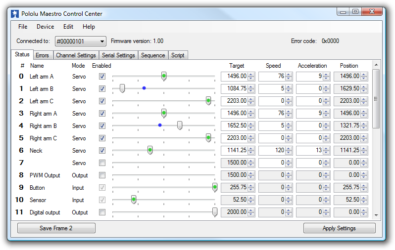 Under the Status tab, you will find the interface for testing out your servos. This lets you send commands to move your servos around without using VSA as explained here. Obviously, this won’t work if you haven’t connected your servo, and the servo power.
 Control Center also lets you set the travel range of your servos (along with more advanced parameters such as max speed and acceleration and the startup position when first turned on). This is confusingly explained here. Maestro refers to the emulation mode as the “8-bit” mode. Like the old Mini SSC II, you can only send position commands ranging from 0-254. But you get to set how that maps to the actual servo travel. “8-bit neutral” sets the center of travel. 1500 is the center for standard servos. Setting 8-bit range to 476.25 will give roughly +/-45 degrees of travel. Changing this to 952.5 will give roughly a +/-90 degree range. As before, you need to be careful to make sure you set limits appropriately. You can do this in VSA, but Maestro boards let you set this directly in Control Center. Our recommendation is that you always set the min to 500 and the max to 2500 in Control Center which allows full range, and do the actual limiting in VSA.
The smaller Maestro boards have a two pin header for connecting servo power. The larger ones have screw terminals. There is no on/off switch.
Tips on Servo Power
In an ideal world, servo controllers would come with servo power supplies the simply plug in, and just work. But they don’t. It’s up to you to buy the right power supply and figure out how to connect it to your board.
Servos are generally rated for 4.8V – 6V supplies, with the actual current draw rarely specified. We suggest you run all of your servos at 5V, for the very practical reason that high current 5V power supplies are inexpensive, and widely available.
Guessing the current consumption in advance is difficult. Servos draw very little power when not under load. But when trying to quickly move something heavy, it shoots way up. A reasonable rule of thumb is that a standard analog servo can draw up to about 1A under load. (Digital servos typical draw several times this.) Smaller servos draw less. Bigger ones draw more. As a starting point, I would recommend a 5V, 4A supply to use with the 6-channel Micro Maestro, and a 5V, 8A supply for the 16-channel Parallax controller. (This presumes that you are unlikely to have all of the servos under full load simultaneously.)
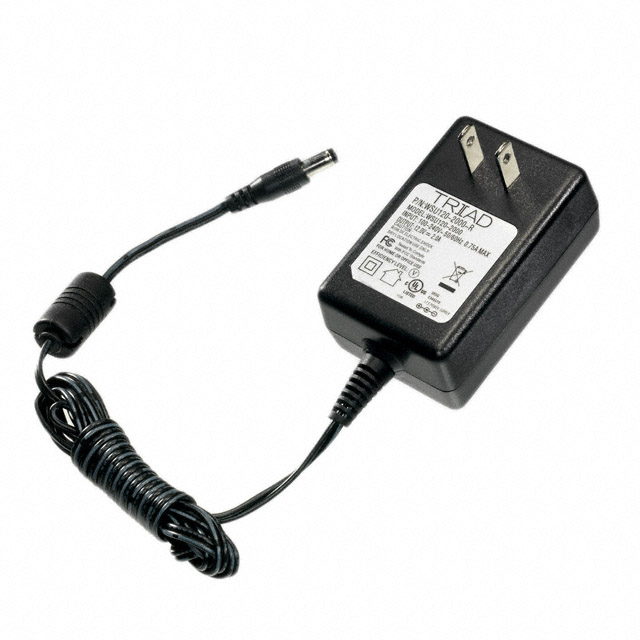 Inexpensive 5V, 4A supplies are fairly easy to find on Ebay. For slightly more money, you can get these from Digikey. Connecting these to the boards can be tricky. There are lots of different connectors, but 2.1mmx5.5mm and 2.5mmx5.5mm, center positive, barrel power connectors are the two most common.
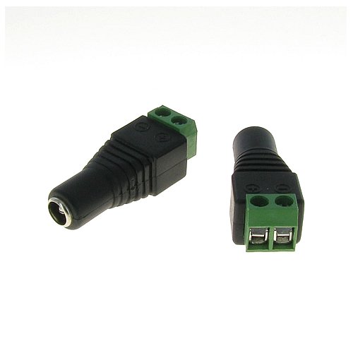 If soldering connectors isn’t for you, you can buy jack screw terminal adapters for these plugs. Here are some examples. To then connect to a 2-pin header, you can cut apart a servo extension cable to get the right connector with wires.
Make sure you get the polarity correct! Getting it wrong will most likely destroy things. Use a meter to check before connecting.
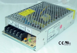
Once you get above 6A, desktop supplies start to get impractical. Instead, an enclosed frame supply such as this seems more reasonable. This is easy to wire to screw terminals, however, it does not come with a power cord. Instead, you have to make one up. And this leaves you with exposed terminals with full line voltage. If you go this route, we strongly recommend that you find a qualified electrician to not only hook this up for you, but also to find an appropriate way to cover the terminals to remove the shock hazard.
Tips on Device Manager
When using servo controllers, it’s easy to forget which COM ports they are connected to. To figure this out, you need to run the Device Manager. Bring up the Start menu and type:
Device Manager
and hit return. Under Ports, you will find a list of the available COM ports.