
In this section we take a brief look at some mechanisms you may use in your animatronic figures. We will start with some very simple mechanisms, and work our way up to more complex ones. By no means is this an exhaustive list. But hopefully this will give you some ideas of how to get started.
 We begin by considering the design of a one degree of freedom (1-DOF) mouth mechanism using a standard size servo. For simplicity, we will fashion a piece that fits directly onto the servo horn and inserts into an upper or lower jaw. This piece will attach to the servo horn via two #6 screws.
 The first step is to prepare the servo horn by making two holes big enough to accept #6 screws. Remove the horn from the servo by loosening the center screw. It is then easy to punch or drill out a couple of holes to the right size. Make sure that the horn is fat enough to support the size hole you are making. For smaller servos, you may need to use smaller screws.
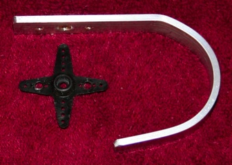
Next, you will need a piece of flat aluminum, cut to the appropriate length. You will need to make three holes – two for the #6 screws, and a larger one to allow access to the servo horn attachment screw. The horns typically have a slight rim around the center. You want to make the center hole just big enough to accommodate this rim. This will allow the metal piece to sit flush against the horn. Because this is a larger hole than you can punch, you will need to drill it.
By creating the large center hole first, you can then use the prepared horn as a template for marking the correct position for the two remaining holes. Simply rest it in the hole (it should lie flush) and mark the two positions. You can then punch the remaining two holes.
The next step is to bend the metal piece into the appropriate shape to fit into the puppet. Be careful not to bend the region which attaches to the horn – it must remain flat. Once you have done this, you may then attach the horn using two #6 screws. The screws are inserted facing away from the servo. This gives the most clearance so the screws won’t scrape against the servo. Place nuts on the screws and tighten. Once you attach the horn/metal assembly to the servo, you won’t be able to reach these screws.
The next step is to attach the assembly you have just made to the servo. This can be tricky because you must attach it so that the range of rotation ends up in the right place. The best thing to do is to attach the servo to a controller and put it in a known position (center, far left, or far right), and then place the assembly on at the appropriate angle for that position. It’s generally not a good idea to turn a servo by hand, but you can often do it without breaking the servo if you are very gentle. This is a quick way to verify the range of motion for the angle you have chosen. When you are satisfied that you have the correct angle, attach the servo horn to the servo via the center screw.
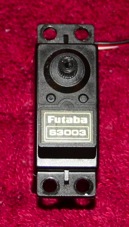 At this point you have a servo which rotates a metal piece, but you have nothing to hold the servo in the right position. You need some sort of bracket that holds the servo in place. A standard size servo has four mounting holes that each fit a #6 screw. This is where you will attach the servo to its bracket.
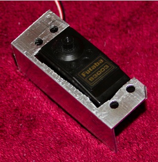 You can fashion a simple bracket from a piece of angle. As before, I recommend beginning with the large rectangular cutout for the servo body. This can be made with a nibbler. You can then use the servo itself as a template to indicate the position of the screw holes. Mark the holes, and then punch them out. This will give you a very sturdy bracket to hold the servo. One thing to watch out for is that the punch can only get so close to the angle wall. If you punch one inner hole first before marking the others, you will then know how close the servo can get inside the angle.
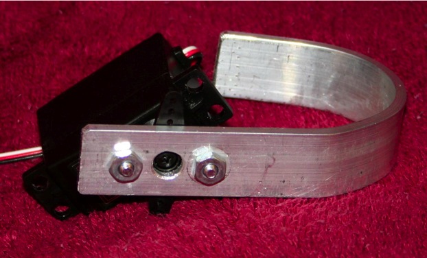
When making an animatronic figure, you will often want to create moving assemblies, which are themselves, movable. For example, a mouth mechanism might be part of a head, all of which can turn. In these cases, you will need to mount entire servo mechanisms on another servo! Raffles was a simple example of such a mechanism. Let’s take a closer look at that figure.
 Raffles is a 2-DOF (2 degree of freedom) figure. The mouth mechanism is mounted on a single bent flat piece which is then mounted on a second, larger servo. That piece extends beyond the servo horn to create the lower jaw holder. These pieces fill the head fairly well, so turning the large servo tilts the whole head. The large servo is then mounted to a large metal strip which is attached to a base.
Making all of these brackets can be rather time consuming. Most of the time, you will need to make your own custom pieces to make things fit. But you should also know that you can buy some pre-made servo brackets and assemblies. These are only available for standard size servos. But they do have some nice features.
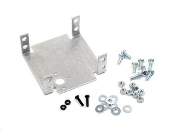
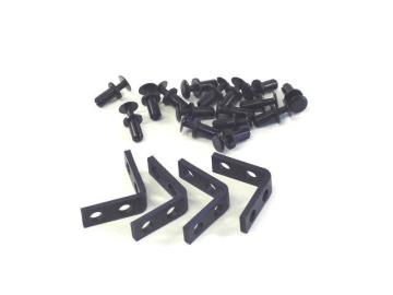
The pre-made brackets we will have available are manufactured by Lynxmotion as part of their Servo Erector Set. The parts we have are:
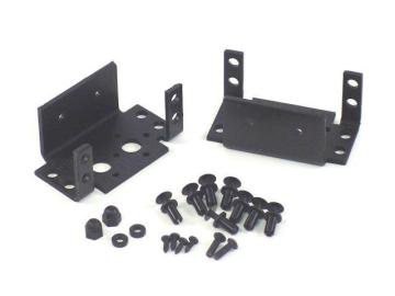
Aluminum Multi-Purpose Servo Bracket
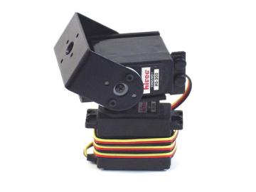
All of these may prove useful in your designs. The Pan and Tilt Kit is particularly interesting. The top rotating bracket is supported on both sides (the side not shown in the picture rotates on a screw bearing), so it can handle heavier loads with better stiffness compared to a bracket supported on only one side. If nothing else, these parts may give you some ideas about how to build mechanisms of your own.